Cooling System Design Tips
Main Considerations
Air Flow, Distribution and System Pressure
The greater the airflow and pressure of a given system, the greater the noise. Total airflow can often be minimized by carefully distributing flow. This is done by placing heat sources with highest power levels where the air stream has highest velocity. Baffles can be used to concentrate airflow on higher power devices and heat sinks to improve transfer of heat to the air stream. Pressure can be minimized by avoiding changes in airflow direction. Air inlet and exhaust ports must not be constricted.
Any close obstruction upstream or downstream to the fan will increase noise, especially obstructions with sharp edges. Choose rounded finger guards when possible.
How Many Fans
In multiple fan applications, lower noise will be achieved by using a small number of large fans, rather than a larger number of small fans.
Fan/Blower Size
Most air movers operate more efficiently at less than their nominal rated voltage. Size the air mover for worst-case thermal conditions. Don’t compromise available airflow. The controller will power the air mover only as necessary to maintain the selected control temperature. Consider allowing maximum flow somewhat greater than for a fixed speed design.
For least noise, an air mover should be selected and its speed set such that it will provide the required airflow and pressure at about 70% of free airflow on its performance curve. Choosing a high-pressure air mover in a low pressure application will result in significantly greater noise. Conversely, a low-pressure air mover heavily loaded in a high-pressure application will also increase noise.
AC or DC?
Choosing an AC or DC fan is generally a matter of power availability. In HVAC applications and in some electronic cooling applications at power levels above 100 watts, AC power is usually preferred. At lower power levels, DC power is usually preferred because it avoids high voltage AC wiring, and provides airflow independent of power line voltage and frequency. All things being equal, nearly all DC fans are speed controllable, not all AC fans are controllable.
SmartFan Nimbus and Nimbus-HP fan controls use a triac phase control principle to vary the voltage applied to the fan. As the figure below illustrates, the voltage applied to the fan is switched off for a period of time, called TOFF and switched on for a period of time TON during each half of one line cycle. As a result, the fan RMS voltage changes proportionally to increases and decreases in TON Since fan speed is proportional to RMS voltage applied, it will also vary in proportion to changes in TON.
Click on image for larger version.
SmartFan Stratus II is a Variable Frequency Drive that controls motor speed by varying the output frequency from 0 to 400 Hz for small single phase or three phase fractional HP motors.
Many permanent split capacitor (PSC), shaded pole, and universal single-phase motors are compatible with SmartFan AC controls. Three phase motors can only be used with the SmartFan Stratus II VFD. Use of SmartFan controls with capacitor start motors, where a capacitor is switched in and out of the motor windings, should be avoided. Confirm controllability with the fan manufacturer before installation or contact CRI customer service for testing recommendations. Attempting to control a fan that is not compatible could cause excessive heating and could permanently damage the fan motor. Click here for AC Motor Compatibility checklist.
The speed of a DC fan is nearly proportional to the DC voltage applied. Lower powered controls use a linear dissipative principle to vary applied voltage. At higher power levels, CRI uses a high frequency switching principle to achieve power efficiency of more than 90%.
Temperature Control & Product Operating Principles
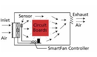
Recommended Control Temperatures based on equipment temperature rise are given in the following table. Temperature rise is measured from equipment air inlet to the point where the sensor is located, often near the exhaust, with air movers running at full speed. These Control Temperatures will result in minimum noise under normal conditions of room temperature, altitude, and system resistance while maintaining lowest operating temperatures under all conditions.
| For this design temperature rise from air inlet to air sensor with air movers running at full speed | 3-6°C | 6-8°C | 8-12°C |
| Choose this Control Temperature | 35°C | 40°C | 45°C |
Recommended Control Temperatures
Recommended Control Temperatures based on equipment application are given in the following table.
35°C Control Temperature
- Larger equipment
- Machine room equipment
- Equipment designed for use in both normal and high temperature environments, e.g., office or storage room
40°C Control Temperature
- Good choice for many purposes
- Equipment of moderate size intended for installation in open offices, hospitals
45°C Control Temperature
- Smaller equipment
- Equipment to be installed in private offices and homes
- Equipment that will be used in proximity to an operator (e.g., desk-mounted)
How SmartFan® Regulates Component Temperatures in Electronic Equipment
A 3° to 4°C temperature change causes a closed-loop SmartFan controller to change speed from idle to maximum. A unit with a 40°C Control Temperature regulates temperature within a range from about 36° to 40°C. In principle, a controller could be made to regulate air temperature more precisely. It would have very high sensitivity such that at a fraction of one degree below 40°C, fans would idle and at 40°C they would reach full speed. There are two reasons why SmartFan sensitivity is controlled at a moderate level. First, very high sensitivity could result in instability (sometimes called hunting) with fans having difficulty finding a stable speed. Secondly, the temperature that we really want to control is that of semiconductor junctions, not air. As the air velocity over a typical semiconductor device (e.g., DIP or similar) changes by two-to-one, as it does when fan speed changes from full speed to idle, the difference between the air temperature and junction temperature changes by a few degrees. Changing the air temperature by an equal number of degrees cancels this effect to hold absolute junction temperature more nearly constant.
Temperature Compensation -The Open-Loop Alternative
An alternative to regulating temperature inside equipment is to sense and compensate for changes in inlet air (room) temperature as shown in the figure below. A disadvantage of such an open-loop system is that it is responsive only to inlet air temperature and cannot respond to changes in power dissipation, altitude, or system resistance. As the curve shows, a change in inlet air temperature from 23°C (73°F) to 35°C (95°F) causes fan speed to change from 50 to 100%. Open-loop versions of SmartFan controllers are available and, like closed-loop units, can reduce noise levels by 15 dB(A) or more.